
WCS-10 Setup Tips Only the Pros Know
The WCS-10 is a sophisticated marine-certified CAN switch bridge that requires precise setup for optimal performance. Professional technicians follow specific protocols that go beyond basic installation guidelines to ensure maximum reliability and functionality. These advanced setup techniques include proper termination configuration, strategic physical placement, optimized message filtering, and professional-grade network structuring. Mastering these professional setup methods ensures your marine CAN-bus systems operate with minimal latency, maximum reliability, and optimal performance even in demanding maritime environments.
Understanding WCS-10: Why proper setup matters for marine applications
The WCS-10 marine-certified CAN switch bridge serves as a critical communication gateway in maritime applications, where system reliability isn’t just desirable—it’s essential for safety and operational efficiency. This sophisticated device enables seamless integration between different CAN-bus networks, allowing various marine systems to communicate effectively.
Professional setup matters significantly because marine environments present unique challenges that can compromise communication integrity. Salt air, vibration, electrical interference, and temperature fluctuations all threaten system stability. Unlike standard industrial applications, marine systems must function reliably in these harsh conditions, making expert configuration critical.
When properly configured, the WCS-10 provides crucial benefits including:
- Isolation between networks to prevent fault propagation
- Intelligent message filtering to optimize bandwidth
- Reliable communication even during power fluctuations
- Protection against environmental factors common in marine settings
The professional approach to WCS-10 setup isn’t merely about connecting wires—it’s about creating a robust communication infrastructure that maintains integrity despite challenging maritime conditions. Expert technicians understand that improper setup can lead to intermittent failures, data corruption, or complete system breakdown when vessels are in critical operations.
How do you properly configure initial settings on a WCS-10?
Proper initial configuration of a WCS-10 requires a systematic approach that professional technicians follow meticulously. Begin by ensuring clean power supply connections with appropriate voltage stabilization—fluctuations common in marine environments can compromise performance if not properly managed.
The physical installation location is critically important. Professionals always mount the WCS-10 in a position that:
- Minimizes exposure to direct water sources
- Provides adequate ventilation to prevent overheating
- Reduces proximity to high-interference equipment
- Allows easy access for future maintenance
- Secures the unit against vibration with appropriate mounting hardware
For the initial configuration process, connect to the device using the recommended configuration tools and verify these essential settings:
- Set the correct baud rates for each network segment
- Configure message filtering parameters based on system requirements
- Verify proper node ID assignment to prevent conflicts
- Set appropriate message forwarding rules between networks
- Implement error handling protocols appropriate for marine applications
Professional technicians always document the baseline configuration after initial setup, which provides a reference point for troubleshooting and enables consistent replication across multiple installations. They also verify configuration by performing a controlled test of all connected systems before final deployment.
What are the common pitfalls when setting up CAN termination on WCS-10?
Proper CAN termination is one of the most critical yet frequently misunderstood aspects of WCS-10 setup. The most common mistake professionals identify is incorrect termination resistance values, which leads to signal reflection issues and communication failures that can be frustratingly intermittent.
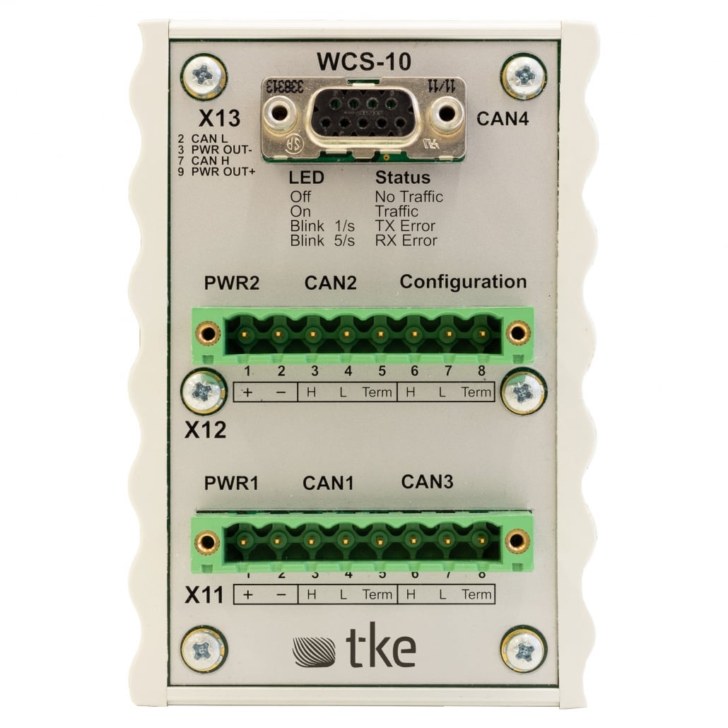
Each CAN bus segment connected to the WCS-10 requires exactly two 120-ohm terminators—one at each physical end of the network. A frequent pitfall is the improper placement of these terminators, with inexperienced technicians sometimes installing terminators at multiple points or using incorrect resistance values. Professional technicians understand that the WCS-10 itself may incorporate internal termination for some ports that must be properly configured via DIP switches.
Other common termination pitfalls include:
- Failing to account for the WCS-10’s internal termination capabilities
- Using poor-quality termination resistors susceptible to marine environmental factors
- Improper shielding connection at termination points, introducing noise
- Neglecting to verify termination with appropriate testing equipment
- Assuming identical termination requirements across different network segments
Professional technicians always verify proper termination using oscilloscopes to check for signal quality and appropriate voltage levels. They understand that termination isn’t just about preventing reflections—it’s about maintaining the integrity of the entire communication system, particularly in marine environments where reliability is paramount.
How can you optimize WCS-10 performance in complex network structures?
Optimizing WCS-10 performance in complex marine networks requires strategic configuration beyond basic setup. Professionals implement intelligent message filtering to ensure only relevant data traverses between network segments, preventing unnecessary bandwidth consumption and reducing system latency.
Network topology design is fundamentally important when working with multiple WCS-10 units. Professional technicians create hierarchical structures that:
- Minimize message hops between critical systems
- Create logical segregation between different vessel systems
- Implement redundancy paths for mission-critical communications
- Balance load across multiple CAN segments
Message prioritization configuration is another professional technique that ensures time-sensitive data receives appropriate handling. By properly configuring the priority mechanisms within the WCS-10, professionals ensure that critical control messages always take precedence over routine status updates.
For complex installations, professionals implement systematic bandwidth management by:
- Analyzing typical message patterns during different operational states
- Configuring appropriate message forwarding rules based on message IDs
- Setting up periodic status message optimization to reduce unnecessary traffic
- Implementing store-and-forward buffering strategies for non-critical messages
Regular performance monitoring after installation ensures continued optimization, with professionals often implementing diagnostic logging to identify potential bottlenecks before they impact system performance.
What troubleshooting methods do professionals use for WCS-10 connectivity issues?
Professional technicians approach WCS-10 connectivity issues with a systematic methodology that quickly isolates problems. They begin with a structured signal quality analysis using specialized CAN bus analyzers that reveal issues invisible to basic multimeters or visual inspection.
When faced with connectivity challenges, professionals follow a layered diagnostic approach:
- Physical layer verification: Checking cable integrity, shield continuity, and connector quality
- Electrical characteristics testing: Measuring termination resistance, signal levels, and common mode rejection
- Data link layer analysis: Examining frame structures, error frames, and acknowledgment patterns
- Network configuration validation: Verifying baud rates, filtering rules, and forwarding configurations
For intermittent issues—often the most challenging to resolve—professionals employ long-term logging with trigger conditions to capture the precise moment when problems occur. This evidence-based approach prevents the guesswork that often leads to incomplete solutions.
Isolation testing is another professional technique where sections of the network are systematically disconnected and reconnected to identify problematic segments. This methodical process is complemented by specialized tools including:
- Protocol analyzers that decode CAN messages in real-time
- Termination testers that verify proper resistance values
- Signal quality meters that measure noise levels and signal integrity
- Configuration validation software that verifies settings against best practices
Professional troubleshooters also maintain comprehensive documentation of all testing procedures and results, creating a valuable knowledge base for future reference and faster problem resolution.
Key takeaways: Implementing professional-grade WCS-10 setups
Successfully implementing professional-grade WCS-10 setups requires attention to multiple critical factors that together ensure optimal performance in demanding marine environments. The foundation of any superior installation begins with meticulous planning that accounts for both current requirements and future expansion.
The most crucial practices professionals employ include:
- Comprehensive documentation of network topology and configuration settings
- Proper physical installation with attention to environmental protection
- Precise CAN bus termination following manufacturer specifications
- Strategic message filtering to optimize bandwidth utilization
- Regular maintenance schedules including signal quality verification
Professional installations also incorporate redundancy planning for critical systems, ensuring that single-point failures don’t compromise essential vessel functions. This approach includes careful consideration of power supply arrangements, network paths, and failure mode responses.
For those seeking to implement these professional techniques, comprehensive technical documentation and training resources are invaluable. Our expertise in CAN-bus technology and marine applications enables the implementation of these advanced approaches for maximizing WCS-10 performance and reliability in demanding maritime environments.
Remember that proper setup is not merely about initial installation—it’s about creating a robust, maintainable system that delivers consistent performance throughout its operational life. By following these professional techniques, you can ensure your WCS-10 installations meet the highest standards of reliability and performance.
Interested in real-world automation solutions?
Browse our case studies to discover how we support safe and efficient operations through smart control and networking systems

