
TCS-10 Installation Checklist You Shouldn’t Skip
 MARIN
MARINA comprehensive TCS-10 installation checklist ensures your CAN switch bridge performs reliably within industrial communication networks. Proper installation of this critical component prevents costly downtime, communication errors, and hardware damage while maximizing network efficiency. Following a structured checklist helps technicians verify each step from pre-installation preparation through final system validation, ensuring all technical requirements are met for optimal performance in industrial environments. This guide walks through the essential checklist items you shouldn’t skip when installing the TCS-10.
Why is a proper TCS-10 installation checklist essential?
A proper installation checklist for the TCS-10 CAN switch bridge is essential because it prevents system failures, ensures network integrity, and maximizes the performance of your industrial communication setup. Without following a structured process, even experienced technicians can miss critical steps that compromise system functionality.
The TCS-10 serves as a crucial component in CAN-bus networks, enabling reliable communication between multiple network segments. Improper installation can lead to intermittent connection issues that are difficult to troubleshoot, data transmission errors that affect system reliability, and even permanent hardware damage in extreme cases.
Following a comprehensive checklist also helps standardize the installation process across your organization, ensuring consistency regardless of which technician performs the work. This standardization is particularly important in complex industrial environments where multiple systems must integrate seamlessly.
Beyond preventing immediate issues, a proper installation checklist creates documentation that proves valuable during future troubleshooting, upgrades, or system expansions. When you know exactly how the system was configured initially, addressing future concerns becomes significantly more straightforward.
What should you prepare before installing a TCS-10?
Before installing a TCS-10, you should prepare a complete toolkit, verify environmental conditions, document your network topology, and confirm system compatibility to ensure a smooth implementation process. Proper preparation prevents delays and complications during the actual installation.
Start by gathering all necessary tools and components:
- Wire strippers and crimping tools for cable preparation
- Digital multimeter for electrical verification
- Appropriate screwdrivers and mounting hardware
- CAN-bus terminators (120 Ohm resistors)
- Shielded twisted-pair cables suitable for CAN-bus connections
- Power supply with appropriate voltage rating
Next, assess the installation environment to ensure it meets the operational requirements for the TCS-10. Verify that the location provides adequate protection from moisture, extreme temperatures, and electromagnetic interference. The mounting location should also allow for proper heat dissipation and convenient access for maintenance.
Document your existing network configuration and plan how the TCS-10 will integrate into your system. Create a detailed diagram showing all connected devices, termination points, and the planned position of the TCS-10. This documentation serves as a valuable reference during installation and future troubleshooting.
Finally, verify compatibility with your existing systems by reviewing the technical specifications of all connected devices. Confirm that communication protocols, baud rates, and electrical characteristics are compatible with the TCS-10’s capabilities to avoid integration issues after installation.
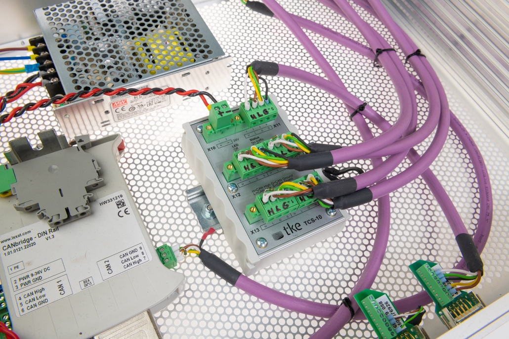
How do you properly connect a TCS-10 to your CAN-bus network?
To properly connect a TCS-10 to your CAN-bus network, you need to follow a systematic approach that includes correct cable selection, proper termination, appropriate power connection, and initial verification of the physical connections before powering up the system.
Begin with selecting the appropriate cables for your installation. Use high-quality shielded twisted-pair cables designed specifically for CAN-bus applications. The cable shield should be connected to ground at one end only to prevent ground loops. Keep cable lengths within the specifications provided in the TCS-10 documentation to maintain signal integrity.
Proper termination is critical for CAN-bus networks. Each physical segment of the network requires 120 Ohm termination resistors at both ends. When installing the TCS-10, verify whether it includes built-in termination capabilities or if external terminators are needed. Incorrect termination is one of the most common causes of communication issues in CAN networks.
Connect the power supply according to the specifications provided in the TCS-10 manual. Ensure the power source delivers clean, stable power within the required voltage range. Consider using a dedicated power supply for the TCS-10 to isolate it from potential interference from other devices.
Before powering up the system, perform these verification steps:
- Check all connections for proper tightness and polarity
- Verify cable shields are correctly grounded
- Confirm termination resistors are properly installed
- Measure resistance between CAN High and CAN Low lines (should be approximately 60 Ohms if termination is correct)
- Ensure power supply voltage is within specified range
Only after completing these verification steps should you power up the system for the first time, monitoring carefully for any unusual behaviour or warning indicators.
What are the most common TCS-10 installation mistakes?
The most common TCS-10 installation mistakes include improper termination, incorrect power supply configuration, inadequate grounding, and network topology errors. These issues can significantly impact system performance and reliability, often leading to intermittent problems that are difficult to diagnose.
Termination errors top the list of installation mistakes. Many technicians either forget to add the required 120 Ohm resistors at both ends of each CAN-bus segment or incorrectly install multiple terminators along the same segment. This improper termination causes signal reflections that corrupt data and prevent reliable communication.
Power supply issues are another frequent problem. The TCS-10 requires a stable power source within its specified voltage range. Using an inadequate power supply or connecting it to a source with voltage fluctuations can cause erratic behaviour or even damage the device. Always verify power quality before connecting the TCS-10.
Grounding mistakes often manifest as mysterious communication errors. Improper shield grounding (connecting shields at multiple points) creates ground loops that introduce noise into the system. Similarly, insufficient grounding protection leaves the network vulnerable to electromagnetic interference and potential damage from voltage surges.
Network topology errors include:
- Exceeding maximum cable length specifications
- Creating ring structures instead of proper bus topology
- Using incorrect stub (drop line) lengths
- Installing too many devices on a single segment
- Using incompatible cabling or connectors
Avoiding these common mistakes requires careful planning, attention to detail during installation, and thorough verification before commissioning the system.
How can you verify a successful TCS-10 installation?
You can verify a successful TCS-10 installation through a series of diagnostic procedures, communication tests, performance validation steps, and systematic troubleshooting if issues arise. Proper verification ensures your CAN-bus network will operate reliably under actual working conditions.
Begin with basic electrical checks using a multimeter to confirm power supply voltage, termination resistance, and absence of shorts. The power LED indicator on the TCS-10 should illuminate when power is applied correctly. If it doesn’t, immediately check your power connections and supply voltage.
Next, perform communication testing between devices on the network. This may require specialized CAN-bus diagnostic tools that can monitor traffic and verify proper signal characteristics. Check that devices on different segments can successfully exchange data through the TCS-10 bridge. Many modern industrial controllers also provide built-in diagnostic capabilities that can help verify proper communication.
Performance validation should include testing under various operating conditions:
- Verify communication at different data rates if your application requires variable speeds
- Test with minimum and maximum message loads to ensure stability under varying traffic conditions
- Check operation at temperature extremes within the specified operating range if applicable
- Confirm proper handling of error conditions by intentionally creating controlled fault scenarios
If you encounter issues during verification, approach troubleshooting methodically. Isolate components by disconnecting sections of the network to narrow down problem sources. Document all test results and any issues encountered for future reference. In complex installations, consider using protocol analyzers that can capture and decode CAN-bus traffic to identify specific communication problems.
What key takeaways should you remember about TCS-10 installation?
The key takeaways about TCS-10 installation focus on thorough preparation, correct connection procedures, proper termination, quality components, and comprehensive testing. Following these critical checklist items ensures your CAN switch bridge installation will deliver reliable industrial communication performance.
Remember that proper preparation before installation prevents most problems. Document your network topology, gather all necessary tools and components, and verify environmental conditions meet specifications. This preparation phase is not just administrative—it’s a critical technical requirement for success.
Pay special attention to termination and grounding. Each CAN-bus segment must have exactly two 120 Ohm terminators (one at each end), and shield grounding must be done correctly to prevent electromagnetic interference. These electrical considerations directly impact signal integrity and system reliability.
Quality matters throughout the installation process. Use proper cables, connectors, and power supplies designed for industrial applications. The minor additional cost of quality components is insignificant compared to the potential expense of troubleshooting and downtime caused by inferior materials.
Finally, never skip the verification steps. Thorough testing after installation confirms that your system will perform as expected under actual operating conditions. Verify both electrical characteristics and communication functionality before considering the installation complete.
For complex installations or when facing challenging network requirements, our technical support team at TKE Sweden can provide additional guidance specific to your application. With proper installation following this checklist, your TCS-10 CAN switch bridge will deliver the reliable fieldbus performance your industrial systems require.
Interested in real-world automation solutions?
Browse our case studies to discover how we support safe and efficient operations through smart control and networking systems

