
Case Study: Extension of the MARIN CAN Network using TCS-10 CAN Switch
When Maritime Research Institute Netherlands built larger and more complex simulations and test facilities they realized that they were limited by the size of the CAN Network and by the length and speed of the CAN bus used to control the test equipment.
To overcome these limitations MARIN successfully used the TCS-10 CAN Switch from TK Engineering to split the CAN bus into segments. This gave them the option to have a longer CAN bus, higher data rates, more flexible network topology and resistance to faults in the CAN network.
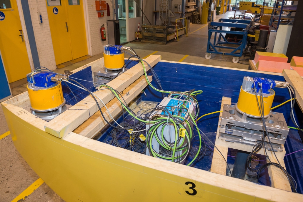
Ship models are controlled by CAN Bus connected servo drives
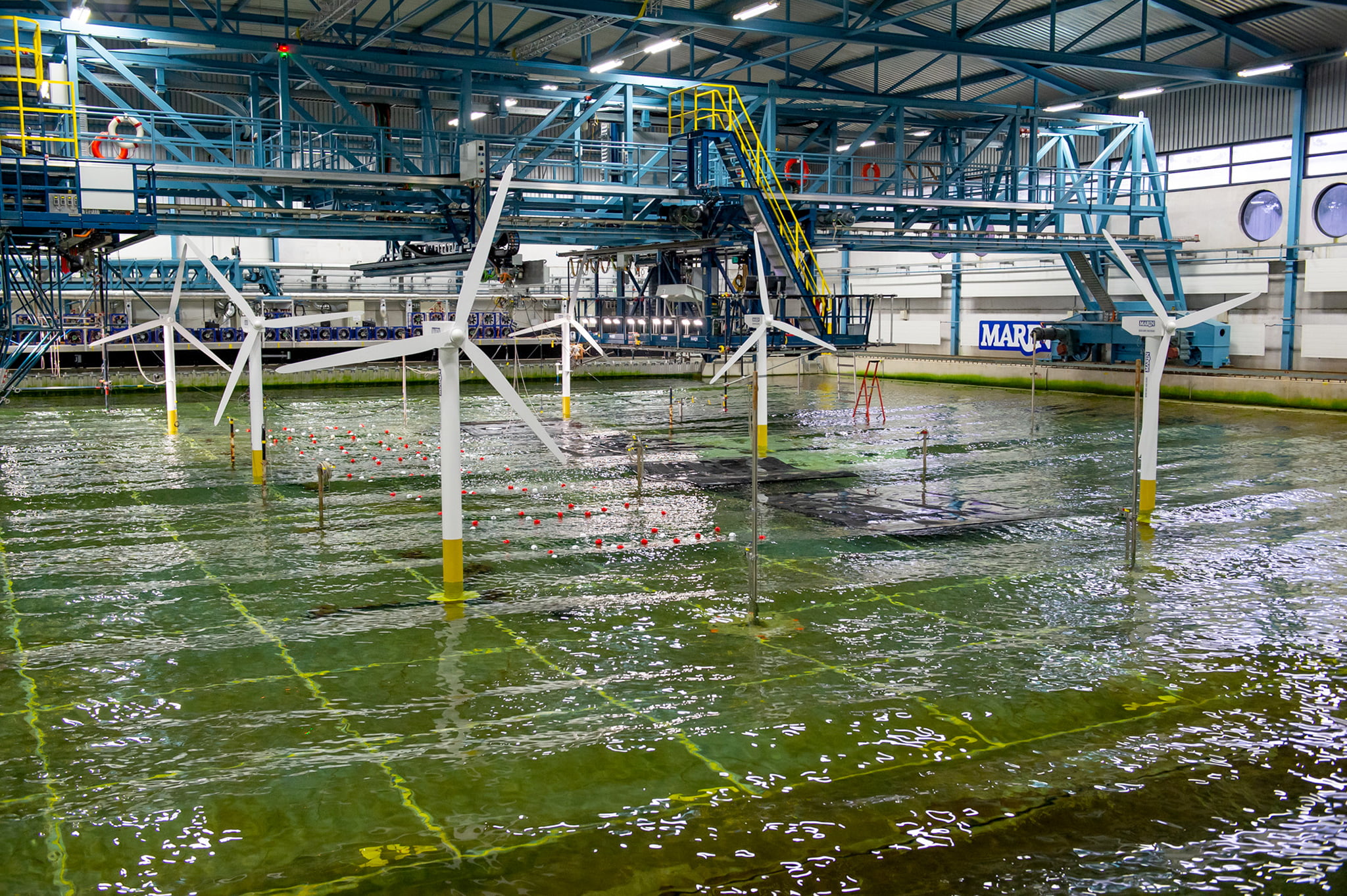
Test of wind turbine models. Photo: MARIN
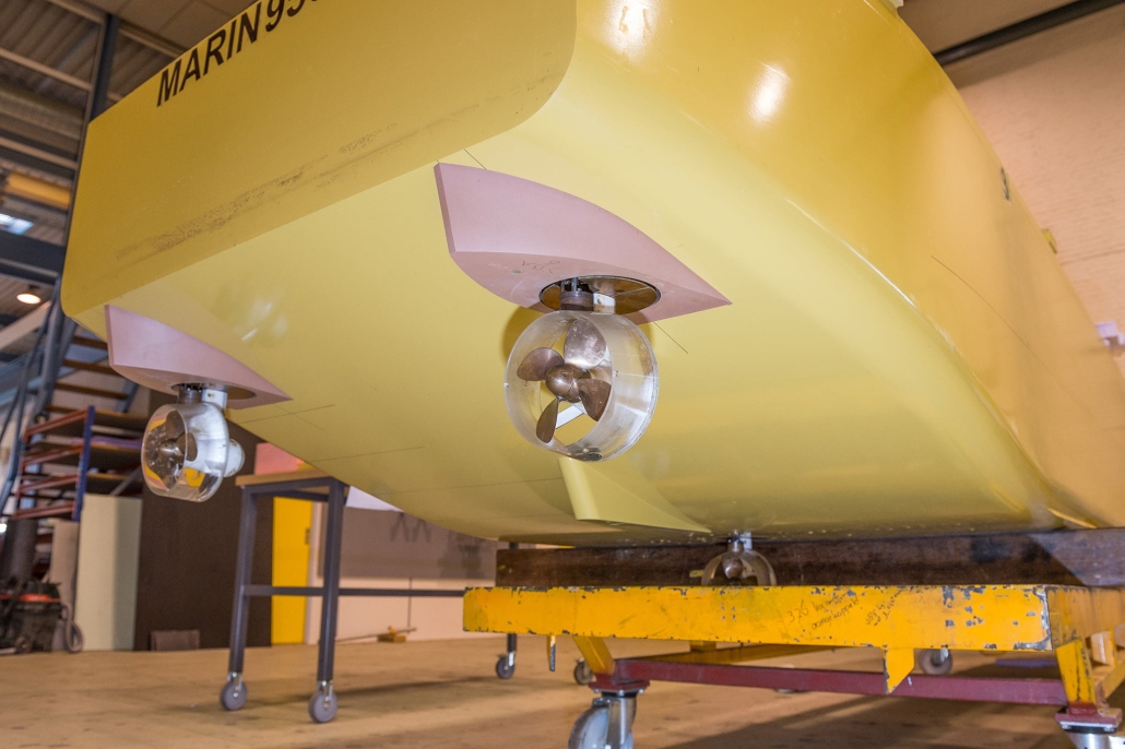
Many MARIN model tests are performed with electrical servo-powered ship models. In the most simple setup, for example a propulsion test, this involves only a propeller. Manoeuvring and free sailing requires additional rudder servo motors. Other actuators such as fins, tunnel thrusters, winches and podded propulsors are used as well, most of the time combined together. These servo drives- and motors are typically developed by MARIN itself to offer the best solution for a test. Most of the time of this equipment must be waterproof, it must have very little backlash but it also must be flexible to (de-)mount in any unique ship model.
In the ship, there are servo motors that are controlled by a software algorithm (auto pilot). This software algorithm provides set points for the propeller rpm and rudder angles based on the motions and position of the model. Position is measured by a 3D infrared camera system, motions are either a derivative or in most cases measured by a rate gyro. Each signal is recorded and handled by a PC running the auto pilot. The resulting set points are transferred via OPC to MARIN software called BSS (‘Basic Steering System’). BSS acts as an interface between the auto pilot and CAN Bus.
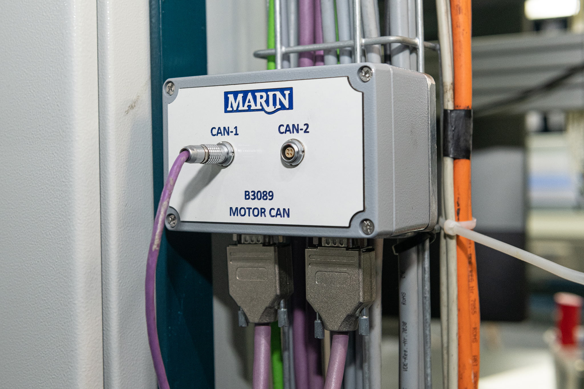
CAN Bus is the MARIN standard field bus for addressing servo drives. It gives us the advantage of a robust, high speed bus system, which can be used over greater lengths in a rugged environment.
More complex models pushing the limits of the CAN network
When CAN bus was first introduced at MARIN in 1999, ship models were not as complex as they are today. Generally, throughout the last decade, an increase in actuators and desired bus speed can be seen. Today, models with 16 fast actuating servo motors are no exception in for example an offshore rig. This increased number of servo drives (or CAN nodes), and also the higher software processing speeds, required a higher bandwidth CAN bus to the point that the bandwidth of the CAN bus is becoming a bottleneck.
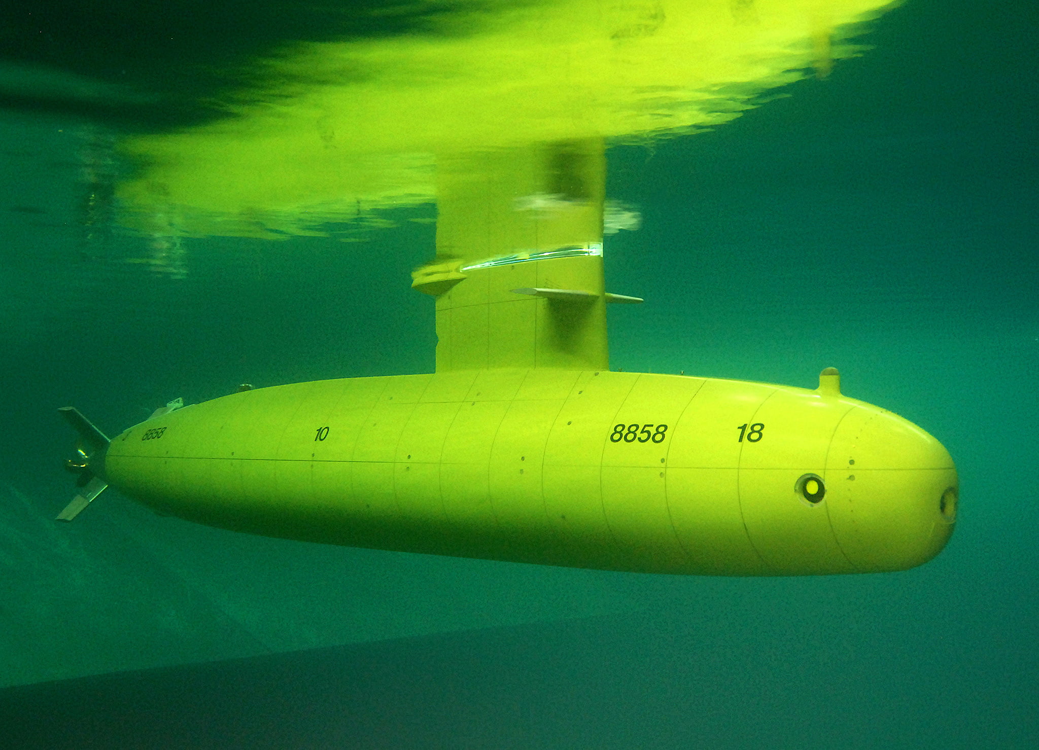
Submarine model. Photo: MARIN
In MARIN’s offshore basin both wind and waves can be generated. To simulate latter, wind fans are used. These are all servo motor equipped fans with an integrated servo drive connected to CAN bus. This is where problems first arose. In order to create a homogeneous wind field, a battery with up to 55 wind fan servos can be used. In a model test a wind spectrum can be applied. This results in a dynamic wind field with for example sudden gusts as it would be in real life. Therefore all wind fan servos continuously receive new set points.
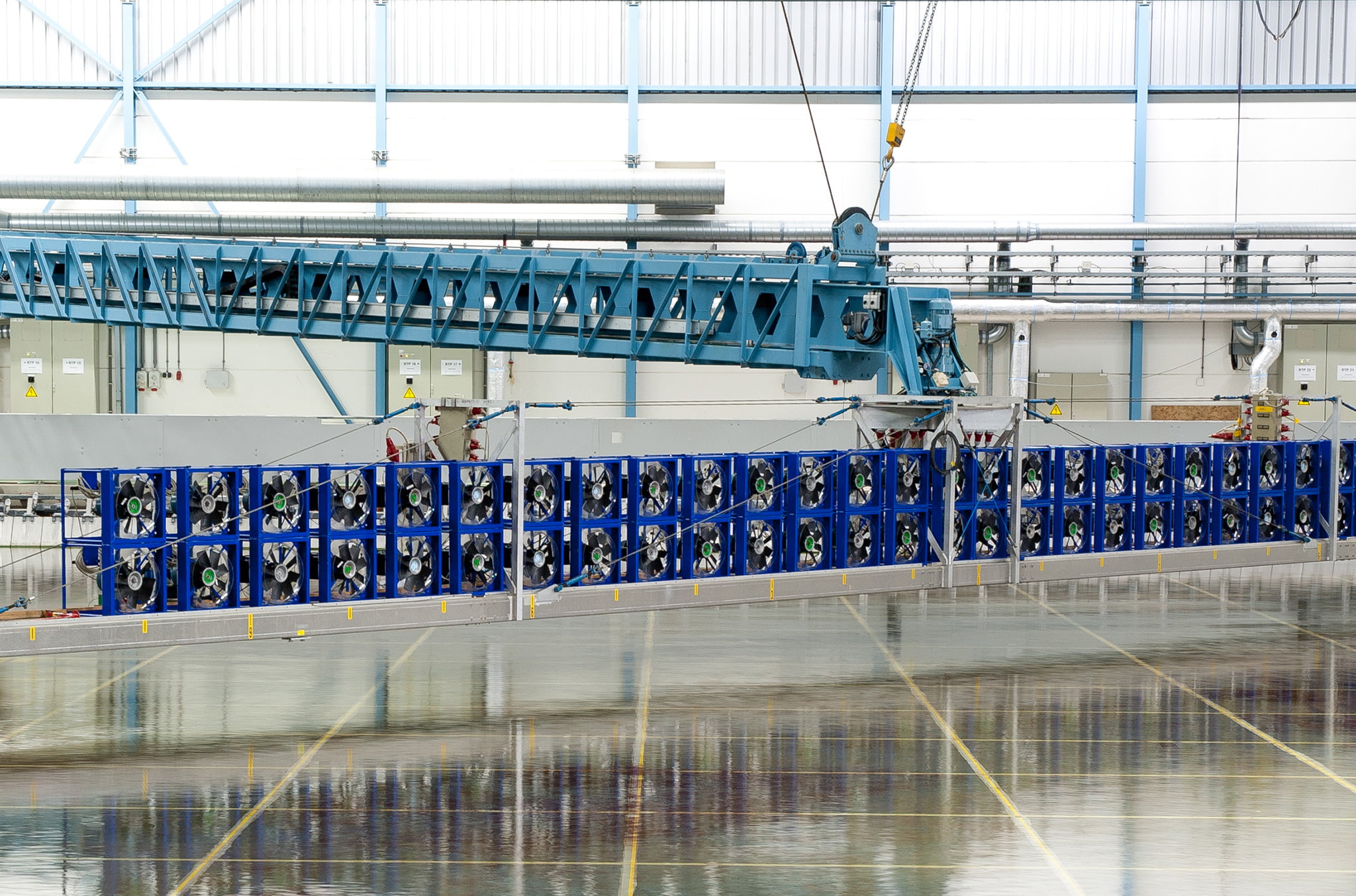
CAN bus connected fans are used to create wind for tests. Photo: MARIN
In the past, all wind fan servo’s were connected to one long CAN bus, with a PC acting as master. In this setup the bus load became critically high, sometimes over the edge of what is allowed. To further complicate things, if one servo drive would fail, as a result the entire bus would fail, ultimately resulting in a complete breakdown. During a model test these breakdowns would create a lot of extra time pressure and costs.
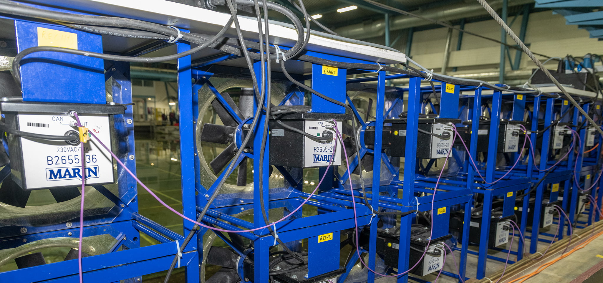
CAN bus connects to every fan in the set: Photo: MARIN
Other facilities also suffered from the high demands in performance, bus load problems with free sailing models, but also distance vs. maximum bit rates (with 125 kbps as the MARIN standard).
More flexibility was needed for CAN network
With CAN being a daisy chain, until recently there was no other option than connect one drive to another, with a terminator at the very beginning- and end of the bus. This affected flexibility (which for MARIN is very important with a changing setup for every test). In case of bus load problems there was little more to do than lowering the bus bit rate but this inconveniently interferes with the model test. In a few cases there even was an additional PC placed with its own CAN bus and software couplings to relevant MARIN systems as a quick fix. This however is very complex and time-consuming.
In general, CAN bus at MARIN network provided a lot of possibilities, but as time went by the increasing demands left the system with room for improvement.
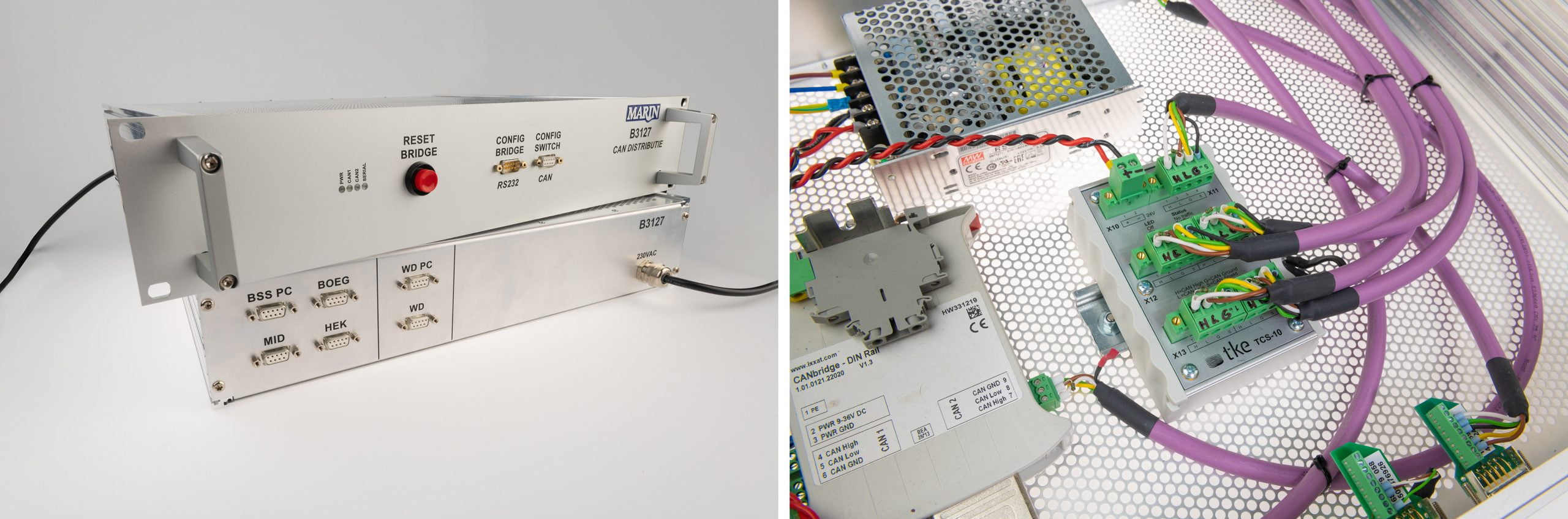
The Solution: Using the TKE CAN TCS-10 Switch to split CAN bus into segments
 MARIN first learned from the TKE CAN Switch entering the market in 2015. The product did seem to offer an ideal solution for the problems we were facing. At that very moment a large overhaul of the Offshore Basin was already in the planning, so a CAN bus upgrade could very well be combined with this overhaul. The units were provided by the Dutch supplier Jonat Automation, and were first borrowed to do some thoroughly testing. After this, a design was made and was implemented in the CAN network infrastructure in the basin.
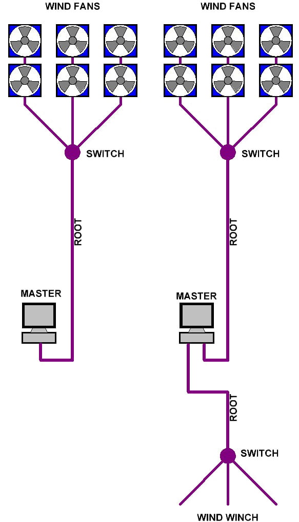
The units were first applied at the wind fans. A CAN switch has 4 ports. Instead of daisy chaining the bus over all fans, the computer (which is about 100 meters away) was connected to one port of the switch. The other three ports were equally divided over the wind battery with each a number of fans. This resulted in a tree-topology with the PC in the root. Port forwarding was applied. Each wind fan section forwards to the root (PC), but not to other sections. In this way CAN messages are filtered and do not disturb other sections
This approach reduces the bus load at the wind fans, but introduces the risk of congestion in the root as well. After all the PC still has to handle all 55 fans. To avoid this the bit rate in the root was increased. The TKE CAN switch can also act as buffer between different bit rates, so locally the MARIN standard bit rate of 125 kbps is retained. By setting the root to 250 kbps, the switch enables this section to handle more traffic.
In the end the TKE switch provided us with a setup with several field connections. Additional benefits are that in case of any problem, this is limited to the section where it occurs (and not the whole wind system). It was observed that a switch port with a forced error frame percentage of 100%, did not affect operation on the other ports. This makes troubleshooting much easier and less time-consuming.
The table below shows some basin test results from the commissioning report. Port 1 is the PC / Master and root. Port 2, 3 and 4 had several servo drives connected. This table clearly shows the advantage of using a port-forwarding switch rather than daisy chaining all nodes on one long bus.
| Test condition | Bus load CAN #1 |
Bus load CAN #2 |
Bus load CAN #3 |
Bus load CAN #4 |
| All ports 125 kbps, no port forwarding (switch acting as a HUB) Although in terms of bus load the switch might seem useless here, there still is an advantage in the fact that the switch can still filter any error message, improving operation. |
19 % | 19 % | 19 % | 19 % |
| All ports 125kbps, forwarding #3 only to #1 Notice the drop in bus load on #2 and #4, which do not have to cope with the #3 CAN frames anymore. |
19 % | 14 % | 19 % | 14 % |
| All ports 125kbps, forwarding #3 only to #1, with some forced extra bus load The bus load reduction on #2 and #4 is here even more visible |
28 % | 15 % | 28 % | 15 % |
| All ports 125kbps, forwarding #2, #3, #4 only to #1 Now the #2, #3 #4 bus load are not affected anymore by each other. Only #1 has to process all the frames. |
23 % | 9 % | 9 % | 9 % |
| Bit rate #1 increased to 500kbps, others 125kbps, forwarding 2, 3, 4 only to #1 Tunnelling the #2, #3 and #4 frames to a higher speed decreases the #1 bus load as well. |
5 % | 9 % | 8 % | 8 % |
Note that these tests were not performed with the entire 55-fan battery active, but only a few per section. The table only illustrates the performance that can be achieved by applying a TKE CAN TCS-10 Switch.
This being a success, more switches were applied. On the bottom of the root another switch was placed to provide for extra field connection points. These are situated right across the basin and are used for winches. Some customers prefer applying a wind force on their model by roped winch rather than an actual wind flow. Both systems are not used simultaneously but could be in theory. In the past a manual switch had to be set, choosing between ‘winch’ or ‘wind’. By inserting a switch this combines the two systems and error chances are reduced.
CAN Switch offers the possibility of using a great number of CAN nodes
On the carriages, switches were applied to provide us several field connection points divided over different places on the carriage. In this way ergonomics benefited; our ever-changing models and test setups asked for flexibility in connection points, and this also reduced the desired cable length, reducing the failure chances even more.
Ever since the TKE CAN Switch was applied at MARIN no more CAN Bus related errors occurred in the test facilities, reducing the downtime to zero. Concluding it can be stated that the CAN Switch offers the possibility of using a great number of CAN nodes, it simplifies the setup and improves flexibility. After the Offshore Basin overhaul, the Seakeeping and Manoeuvring Basin followed. Currently a proposal for upgrading the CAN topology in other test facilities has already been approved and is awaiting a maintenance stop during which all new hardware can be installed.
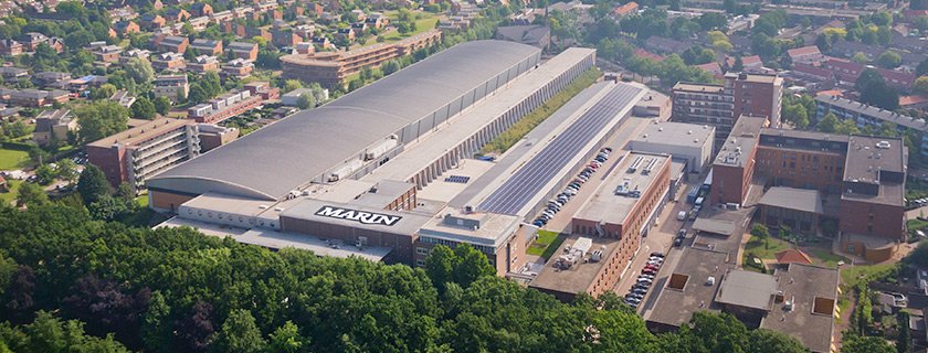
About MARIN
Maritime Research Institute Netherlands is a provider of advanced expertise and independent research. Through the use of the newest test facilities, full-scale measurement and simulators and working together with an extensive innovation and research network we achieve our goal: the development of cleaner, safer and smarter ships and sustainable use of the sea. MARIN is based in Wageningen and employs a staff of 400.
About TK Engineering
TK Engineering provides expert services related to CAN (Controller Area Network) technology. TK Engineering works together with the market leaders in the Marine, Rail, Machinery, Heavy vehicles and Defence industries to design CAN hardware and software and combine them with various technological systems.
About Jonat Automation
Jonat Automation provides engineering and consultancy services for industrial automation projects, specializing in CAN bus and machine vision. Jonat Automation is a distributor of TK Engineering’s products in the Netherlands.

