Systematic re-use of information
Systematic re-use of information and design processes defined by the selected system integration framework, such as CANopen, should be understood as an integral part of companies’ design, assembly and service operations, instead of “just another communication protocol” in individual control systems. There are many use cases for such kinds of system integration framework in system design, assembly and service activities.
Eliel Saarinen, a Finnish architect, said: “Always design a thing by considering it in its next larger context – a chair in a room, a room in a house, a house in an environment, an environment in a city plan.” That also applies to system design.
The core of the design process is a set of standardized file formats for storing design information in different phases of the projects, enabling various levels of re-use. There is also a comprehensively defined application programming interface (API) for accessing CANopen communication services from IEC 61131-3 applications to enable the use of device-independent applications. The communication database (DBC) is not standardized, but it is the de-facto format for describing network communication, mainly for network analyzers to enable the visualization of communication in a format that can be understood by humans.

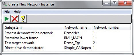
Figure 1: An example user interface for selecting the target subsystem instance from a list updated in conceptual design phase
Of course, it is recommended to design CANopen systems by following the standardized design process. But systems can also be configured device by device, stored in individual device settings as DCF files, and used during assembly and service. After designing the first system, the question arises how to efficiently use the information during assembly and service. Another question is how to re-use this information in the following design cycles and system projects.
The main focus of this article is on the re-use of design information within one single CANopen project or between CANopen projects. It is also considered how design information of other disciplines may be systematically used in CANopen projects and vice versa. This approach also emphasizes the possibilities of linked reference data, programmable system data management, and validation. This is in line with the mainstream SW development principles. Systematic re-use means not only the reduction of design efforts but also the reduction of failure costs.

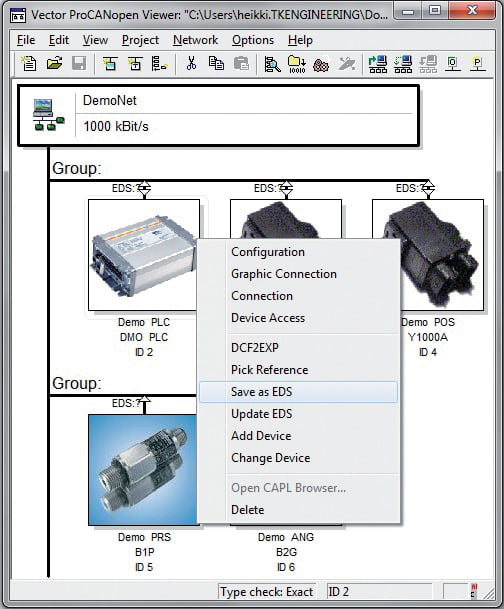
Figure 2: Example system tool with “Save as EDS” command highlighted
Exporting from CANopen projects
Re-use information from CANopen projects is straightforward, thanks to the thoroughly standardized file formats. Various use-cases are published and generating communication abstraction layers for applications is the most widely used export. The generic approach utilizes all information existing in CANopen projects, including signal scaling and units. Further improvements, such as management of parameter access paths and error codes, have also been investigated and proposed as future versions of corresponding standards. In addition to the generic approach, there are also vendor specific frameworks on the market, mainly supporting application development only and excluding device configuration management.
Though configuration downloads from DCF files to CANopen devices have been included in the scope of CANopen, generic CANopen tools do not commonly support a completely automated approach with layer setting services (LSS) and program download support. There are few details that cannot be solved by using DCF files only. Templates with most of the required information can be generated directly from the CANopen projects, but in some cases manual work might be required. Systematic approaches integrated into CANopen system design processes and tools have already been published. It can be concluded that the better the latest CANopen features are supported, the less manual work is required.
It has also been investigated how structural information of systems can be composed from multi-disciplinary projects. The use of additional, system level mechanisms, such as reference designators, is required to enable the recognition of common components between disciplines. Thanks to its standardized project structure, CANopen was the easiest discipline, but e.g. for electric design, standardized interfaces do not exist. Thus, specific export plugins for each CAD program need to be developed.
Re-use of entire subsystems
It is efficient to re-use entire subsystems in larger systems. In practice, only one version needs to be designed by always using the network-ID and network name of the first version. Following versions can be generated from the first one, by modifying the network name and network- ID. Several members of a product line may share the subsystems without modification, when network name and network-ID remain the same. The systematic process expects the definition of each version in the conceptual design phase. An example tool shown in Figure 1 lists the possible target subsystems, defined in a central repository.
The procedure of reuse is simple. After selecting a source project, a target project a and target folder, each DCF file of the source project has to be copied to the target folder first. Next, the network-ID and network name must be updated into each target DCF file. Finally, the nodelist.cpj project file has to be created in the target folder. If alternative devices are supported, all DCF files in the project folder must be copied, not only files listed in nodelist.cpj. With an example tool the whole copying process takes only a few seconds. If an older project is used as a source, after the copying process some devices may need to be changed into new models, for which a systematic approach already exists.
Re-use of device parameters
Quite often there is a need to re-use configurations between devices. If a device becomes obsolete or needs to be changed for a cheaper or better one, the rest of the project typically remains unchanged. It means that the part of the system integration interface that is in use, needs to be supported by potential alternative devices. Various compatibility levels require different approaches.
In the best-case scenario, the new device has an identical system integration interface. A good example can be found in single-coil valve drivers, where the only difference is in the coil connector. In this case, communication related parameters can automatically be copied from the original device. After setting the correct communication, the device settings must be set. Because of the one-to-one compatibility, settings can be imported by a device editor directly from the DCF file of the original device into the DCF file of the new device [8]. Human mistakes can be avoided when settings are imported with a tool instead of manual copy and paste.
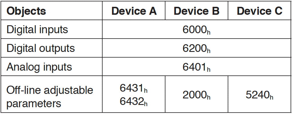
Devices following device profiles are so similar that in most cases the most essential parameters can be imported. The first obstacle may arise when special features of the original device are in use. A second obstacle may arise when rarely supported optional parameters are used. For example, most vendors and models support the most common interface of pressure transmitters. As long as default pressure data type is used and no other parameters than measurement unit and number of decimal digits, one transmitter can be replaced by another independent of their configuration. The most difficult case occurs when the old and new devices share only the signals. Then the alternative devices need to be configured to support equal signal scaling and units. Parameters are often at least partially different and for compatibility reasons, it is not a good idea to access device specific parameters in the target system, because it efficiently decreases the drop-in replaceability. Table 1 provides an example for this approach, consisting of three different I/O devices with fully compatible CANopen communication and M12 connector interfaces.

Table 1: Comparison of three drop-in replaceable general purpose I/O-devices with completely different off-line adjustable parameters
Re-use of devices
Changes to the system integration interfaces during system design may be required for many reasons. Generally, transformation from DCF back to EDS mostly applies to application programmable devices, whose EDS files contain application specific signal and parameter objects. So-called Dynamic Channels may be used for signals, which means that network variables are defined during the system design phase. Alternatively there might be missing or erroneously defined signal or parameter objects in the profile databases created from specifications and in the EDS composed of the profile databases. Due to the constraints of the system design tools, it might be faster to make small changes directly to the DCF files in the system project and synchronize the changes into the original EDS file. Synchronization is required to keep the project structure consistent and to maintain re-usability. The translation from DCF to EDS is simple. The attribute LastEDS from the FileInfo section and the whole DeviceComissioning section must be removed. The attributes ParameterValue, Denotation, and ClientX of each object must also be removed. Additionally, the attribute FileName in the FileInfo section must be updated.
The translation from DCF to EDS can be performed manually by opening a DCF file with an EDS file editor and saving it as an EDS file. A more systematic approach for translation has also been evaluated. An automatic translation from DCF to EDS can be automated by using the CANopen tool’s integration mechanism and the existing information of the EDS file, from which the DCF file has been generated. A major risk in the fully automated translation is an unintended change of the original EDS file if it is named automatically for each DCF.
A safer approach is to use the CANopen tool integration mechanism but let a designer trigger the translation manually from the system design tool, as shown in Figure 2. The safest but also most inefficient approach is to only enable transformation into a new EDS file. CANopen tool calls are included in the EDS and DCF files, which enables limiting the availability of the translation only to the devices requiring such a feature. Based on the measurements, translation speedup is at least in factor of 100 – even with a small DCF, manual translation may take at least 15 minutes while a tool makes it in less than 1 second.
Re-use of applications
CANopen profile databases (CPD) enable the description of parts of the devices object dictionary. Profile databases may be used as a standardized mechanism for the management of device interfaces in a modular way. Signal and parameter definitions may be managed manually, in requirement management systems, or in various kinds of models. A commitment to the standardized transfer format enables starting with a document-based approach and moving further into model based design, without a need for modifications in the detailed design.
In case of changes made during later phases of the project, it is important to avoid additional workloads by automatically synchronizing changes backwards. When the changes in the system integration interfaces are synchronized back into profile databases, interface descriptions may be re-used in the application or function level. If a model-based design is used, changes may be synchronized from the profile databases back to the model to keep it up-to-date.
The translation from an EDS file into profile databases is technically straightforward: It is simply a conversion from one description format of selected parameters into another format. However, there are some open issues on how to handle the original modular structure. First, a standardized mechanism for indicating from which profile databases the EDS file has been constructed and how the objects have originally been divided into modules does not exist. Parameter objects are easily divided into dedicated groups, but signals are located into sub-objects so that the main object depends on the data type. Therefore, other criteria than the object index must be used. One option may be an attribute PP-Offset, which defines the absolute offset of the signal object in the process image. Another option could be the use of additional entries in the EDS and DCF files, but there is a compliance risk because such objects are not standardized.
The use of object dictionary areas in compliance with CANopen is well defined. Signals to and from applications are updated through so-called network variables. There are signal data type and direction specific objects defined, providing access to the same memory area. The value of the attribute PP-Offset defines how the data type specific network variable areas are organized in the process image. The first problem is that multiple types of network variables may point to the same area of the process image. The second problem is that PP-Offset attributes may not be available because network variables are assigned into objects already in the EDS or profile database.
While fully automatic DCF to EDS translation introduces risks, automatic EDS to CPD conversion introduces comparable risks. Therefore only manually triggered translations with object index based filtering have been implemented. They provide significant speed-up and do not lead to complex and proprietary design rules. Based on these measurements, computer- aided translation according to an example in Figure 4 increases the efficiency by a factor of 60 or more, depending on the size of the EDS file and the number of resulting profile databases.
Import to CANopen projects
Parameter and signal descriptions for applicationprogrammable devices can be transferred from specifications into designs as profile databases. Profile databases are an excellent entity for such purposes, because each one defines a subset of an object dictionary and thus does not have any dependencies on the target HW- or SW-platform. The profile database format is not the most convenient one to be edited manually. Profile databases can be viewed but not edited with spreadsheets, because comment lines may reserve whole lines and will not contain separator characters. Furthermore, standardized file headers have to be maintained manually.

Figure 4: Example of extracting manufacturer specific objects into a separate profile database
designators are commonly used in the industry for identifying system components. Each logical position has a unique identifier, a reference designator. Because they are technologically independent and exist in design documents of each relevant discipline, they can be used for combining discipline-specific design documents into a common, multi-disciplinary design entity. In addition to creating design documents, reference designators can be used to validate the consistency of the documents. Reference designators are currently only used for certain subsets of components and disciplines, but the actively used approaches may easily be improved. Furthermore, reference designators are manually maintained and written into each design document. To avoid inconsistencies caused by human mistakes and to increase efficiency of design work, reference designators should be stored into a central repository, where they can be picked for the designs, instead of being written manually. Many design tools require the use of their internal mechanisms, but due to the standardized project files, a system design tool independent pick-up tool, such as presented in Figure 3, can be used with CANopen projects.
Compiled application software can be linked into DCF. Download objects are of the data type domain. The name of the file to be downloaded may be given as a DownloadFile attribute. When the compiled application is linked to the configuration, download tools can first download the application and then the corresponding parameter values as a single operation from the user’s point of view.
Summary
Standardized storage formats of design information enable almost unlimited possibilities for the programmable management and re-use of information from within and to CANopen projects. These notions are in line with the approach to Industrial Internet, where machine-understandable and enriched design data is the key to successful and modern services. In addition, EDS and DCF files enable seamless integration of the supporting tools into the design process. The rich re-use information contents of the standard files serve well as a multi-disciplinary design approach by supporting architecture level information, in addition to the communication description. Current design tools do not provide all features, but they support open, standardized interfaces for filling the gaps.
Systematic design information management significantly improves the efficiency of each phase in the process, moving focus from the management of the raw files to the management of the system level design issues. Further improvement can be achieved by re-using various kinds of design entities, which are stored by using standardized information contents. Information exchange based on standardized contents enables easy crossing of geographical and organizational borders. Instead of the improvements achieved in the design process, the most significant improvement comes from reduced failure costs caused by inconsistent or outdated information, especially in assembly and service.


