
How do I configure a U100 for single-channel CAN monitoring?
Configuring a U100 for single-channel CAN monitoring involves connecting the device to your CAN network, installing the necessary drivers, and configuring the software settings. This process typically requires connecting the U100 to your computer via USB, attaching the appropriate CAN connector to your network, installing the Kvaser drivers, and configuring your CAN monitoring software with the correct bit rate and filtering options. The U100’s rugged design makes it particularly suitable for industrial environments where reliability is essential for effective monitoring of CAN bus communications.
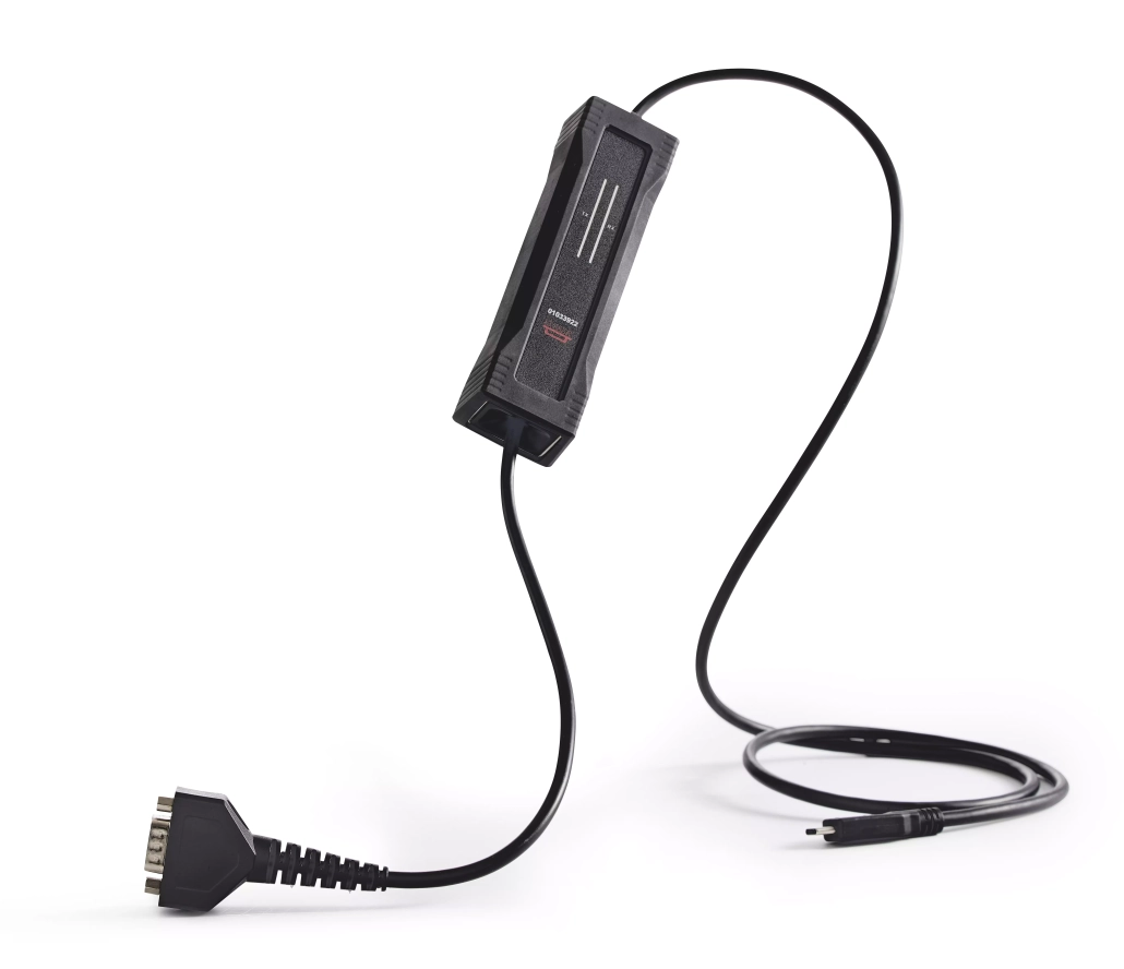
What is the Kvaser U100 product line and its capabilities?
The Kvaser U100 product line consists of compact, USB-connected CAN interfaces designed for monitoring and analyzing CAN network traffic in various industrial and automotive applications. These devices feature a rugged design that makes them ideal for harsh environments while maintaining reliable performance.
The U100 family includes several variants: the standard U100, the U100P with galvanic isolation, and the U100P-X with extended temperature range capabilities. Each model is built to withstand challenging conditions with robust electromagnetic protection, making them suitable for industrial settings with high levels of electrical noise.
These interfaces support both classical CAN and CAN FD protocols, allowing users to monitor both standard and high-speed CAN communications. Their compact form factor makes them portable for field use, while their durability ensures consistent performance in test labs, vehicle diagnostics, and manufacturing environments. The entire product line features USB connectivity for easy integration with various computer systems and software platforms.

How do I configure a U100 for single-channel CAN monitoring?
Configuring a U100 for single-channel CAN monitoring involves a straightforward process that begins with the physical connection and concludes with software setup. Follow these steps to properly configure your device:
- Physical connections: Connect the U100 to your computer using the provided USB cable. Then connect the CAN port on the U100 to your CAN network using the appropriate connector (typically a 9-pin D-SUB for the standard U100).
- Power requirements: The U100 is USB-powered and doesn’t require additional external power sources, making it convenient for portable monitoring applications.
- Driver installation: Download and install the latest Kvaser drivers from the official website. These drivers are essential for your computer to recognize and communicate with the U100 device.
- Software configuration: Launch your preferred CAN monitoring software (such as Kvaser CanKing or third-party applications). Select the U100 from the list of available interfaces.
- CAN bus parameters: Configure the appropriate bit rate to match your CAN network (common rates include 250 kbps, 500 kbps, or 1 Mbps for classical CAN). For CAN FD networks, you’ll need to set both the arbitration and data bit rates.
- Bus connection: Within your software, enable the bus connection to begin monitoring CAN traffic. You should now be able to see messages flowing on the bus.
For optimal monitoring, ensure your CAN network termination is properly configured (typically 120 ohm resistors at both ends of the bus). This helps maintain signal integrity and prevents reflections that could corrupt data.
What are the differences between U100, U100P, and U100-C models?
The U100, U100P, and U100-C models offer distinct features tailored for different CAN monitoring applications. Understanding these differences helps in selecting the most suitable device for your specific requirements.
| Model | Key Features | Connector Type | Best For |
|---|---|---|---|
| U100 | Basic model, USB-powered, CAN FD support | 9-pin D-SUB (male) | Standard laboratory environments, basic monitoring |
| U100P | Galvanic isolation (1000 V), enhanced EMC protection | 9-pin D-SUB (male) | Industrial environments with electrical noise |
| U100-C | Compact design, M12 connector, IP67 rating | 5-pin M12 connector | Harsh environments, outdoor installations, automotive |
The standard U100 is ideal for general CAN monitoring applications in controlled environments. The U100P offers galvanic isolation, providing protection against ground loops and voltage differences, making it the preferred choice for industrial settings where electrical isolation is critical.
The U100-C stands out with its M12 connector and IP67 rating, making it water and dust resistant. This makes it particularly suitable for outdoor installations or environments where exposure to moisture and particulates is a concern. The U100-C’s rugged design ensures reliable operation even in the most challenging conditions.
How does the U100 perform with CAN FD versus classical CAN?
The U100 series delivers excellent performance with both CAN FD and classical CAN protocols, though there are notable differences in handling capabilities. With classical CAN, the U100 supports the standard data rates up to 1 Mbps with reliable message handling and minimal latency.
When operating with CAN FD, the U100 can achieve significantly higher data rates—up to 8 Mbps in the data phase—allowing for more efficient monitoring of high-bandwidth applications. This makes it particularly valuable for modern automotive systems and industrial networks that utilize CAN FD’s expanded capabilities.
The U100’s buffering capabilities ensure minimal data loss even during high-traffic periods on CAN FD networks. Its hardware timestamping maintains accuracy across both protocols, which is crucial for precise timing analysis. However, when working with CAN FD, users should be aware that higher data rates may require more careful attention to cabling quality and termination to maintain signal integrity.
For applications that alternate between CAN FD and classical CAN, the U100 offers seamless switching between protocols through software configuration, eliminating the need for hardware changes when moving between different CAN network types.
How can I integrate a U100 with embedded systems like Raspberry Pi?
Integrating a U100 with embedded systems such as Raspberry Pi provides a powerful combination for CAN monitoring in compact, field-deployable solutions. To successfully implement this integration, follow these guidelines:
First, connect the U100 to your Raspberry Pi using a standard USB port. For the software side, install the appropriate Linux drivers for Kvaser interfaces on your Raspberry Pi. These drivers are typically available through the SocketCAN framework, which provides a standardized interface for CAN devices in Linux environments.
After installing the drivers, you’ll need to configure the SocketCAN interface using commands like:
- sudo ip link set can0 type can bitrate 500000
- sudo ip link set up can0
For embedded applications, you can develop custom monitoring software using programming languages like Python with the python-can library, which offers straightforward access to CAN interfaces. This allows you to create tailored monitoring solutions or data loggers that can operate independently in the field.
Power management considerations are important when using the U100 with battery-powered Raspberry Pi setups. The U100 draws power from the USB port, so ensure your power supply can handle both devices, especially for long-term monitoring applications.
What are the key takeaways for successful U100 CAN monitoring?
For successful U100 CAN monitoring implementations, several best practices should be followed to ensure optimal performance and reliability. First, always use high-quality cabling with proper shielding to minimize electromagnetic interference, particularly in industrial environments where signal integrity is crucial.
Proper termination of the CAN bus (with 120 ohm resistors at both ends) is essential for preventing signal reflections and ensuring clean data capture. When monitoring high-speed CAN FD networks, this becomes even more critical to maintain signal quality at elevated data rates.
Regular firmware updates for your U100 device ensure you have the latest bug fixes and performance improvements. Similarly, keeping your driver software updated helps maintain compatibility with newer operating systems and monitoring applications.
For complex monitoring scenarios, consider using advanced filtering capabilities in your software to focus on specific message IDs or data patterns, reducing the processing load and making analysis more efficient. When troubleshooting communication issues, the U100’s error frame detection capabilities can help identify problems on the CAN bus.
For a deeper understanding of how these devices perform in real-world scenarios, we encourage you to explore our case study section, which provides practical examples of successful implementations across various industries.

